Hydraulic symbols
General symbols
| Graphic symbol | Description |
|---|---|
 | direction of flow and hydraulic agent designation |
 | direction of flow and pneumatic agent designation |
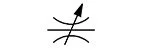
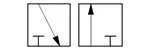
 | variable or adjustable (pomp, spring, etc.) |
 | rotary motion (arrowhead indicates possible direction of rotation) |
 | line (supply or return) |
 | line (pilot, drain) |
 | frame of several components forming a unit |
 | mechanical element (shaft, lever, piston rod) |
Symbols for energy conversion components
| Graphic symbol | Description |
|---|---|
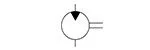
 | fixed displacement pump with one direction of low |
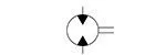
 | fixed displacement pump with two directions of flow |
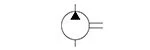
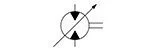
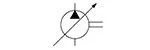 | variable displacement pump with one direction of low |
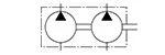 | two-stream pump |
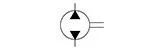
 | fixed displacement motor with one direction of low |
 | fixed displacement motor with two directions of low |
 | variable displacement motor with two directions of low |
Symbols for energy accumulation
| Graphic symbol | Description |
|---|---|
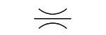
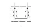
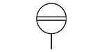
 | hydraulic accumulator (vertical position only) |
 | gas charged hydraulic accumulator |
Symbols of hydraulic cylinders
| Graphic symbol | Description |
|---|---|
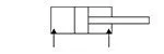
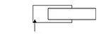 | single-acting plunger cylinder |
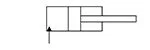 | single-acting single rod end cylinder |
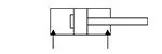
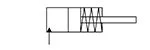 | single-acting single rod end cylinder with spring-loaded piston return |
 | double-acting single rod end cylinder |
 | double-acting single rod end cylinder with left stroke position fixed cushioning |
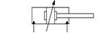 | double-acting single rod end cylinder with both stroke positions adjustable cushioning |
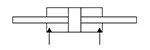 | double-acting double rod end cylinder |
Symbols for pressure control components
| Graphic symbol | Description |
|---|---|
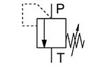 | pressure relief valve pressure limiting valve (safety or overflow valve) |
Symbols for flow direction control components
| Graphic symbol | Description |
|---|---|
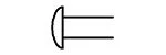
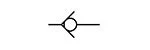 | check valve (non-return) |
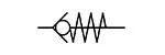 | spring-loaded check valve |
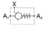 | pilot-operated check valve allowable flow direction: A1 → A2 (free flow) A2 → A1 (provided with X pilot signal) |
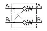 | double pilot-operated check valve (hydraulic lock) allowable flow directions: A1 → A2 and simultaneously B2 → B1 B1 → B2 i and simultaneously A2 → A1 |
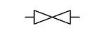 | shut-off valve |
Symbols for hydraulic oil collecting, preparing and conditioning components
| Graphic symbol | Description |
|---|---|
 | Reservoir/Tank |
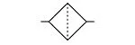 | Filter |
 | Cooler |
Symbols for flow rate control components
| Graphic symbol | Description |
|---|---|
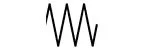
 | fixed throttle valve fixed flow restriction independent of medium viscosity |
 | fixed throttle valve flow restriction depend on medium viscosity |
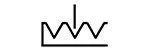
 | adjustable throttle valve flow restriction depend on medium viscosity |
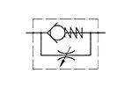 | throttle check valves |
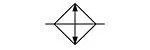
 | flow divider |
Symbols for instruments and indicators
| Graphic symbol | Description |
|---|---|
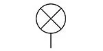 | pressure indicator |
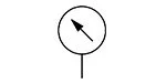 | pressure gauge |
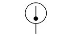 | thermometer |
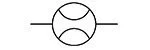 | flow meter |
 | level gauge |
Directional control valve symbols – CONTROL SYMBOLS
| Graphic symbol | Description |
|---|---|
 | general symbol |
 | hand lever |
 | spring |
 | button |
 | three-position detent |
 | solenoid with one coil |
 | solenoid with two coils acting in opposing directions |
 | hydraulic control |
 | proportional hydraulic control |
 | pneumatic control |
 | proportional pneumatic control |
Directional control valve symbols – POSITION SYMBOLS
| Graphic symbol | Description |
|---|---|
 | two position directional control valve |
 | three position directional control valve |
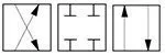
 | two lines connected – open path arrow indicates direction of medium flow (from higher to lower pressure) |
 | two lines closed – closed path |
 | three-way valve (examples) |
 | four-way valve (examples) |


