Hydraulic directional control valves

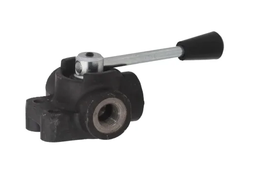
Monoblock spool directional control valves controlled with a manual lever or solenoid with centring springs. Designed for the hydraulic systems of cranes, hoists, construction machinery, agricultural machinery, etc. Equipped with type C safety valve (set to 140 bar) and type 1 spools (for double-acting actuators) as standard.
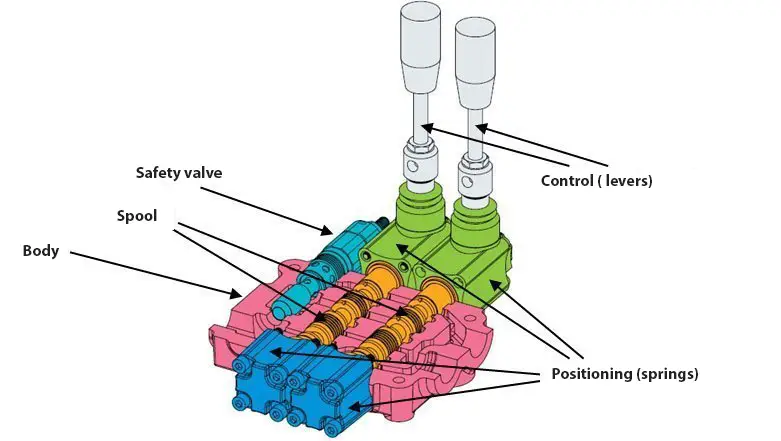
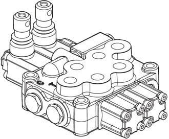
Construction of a directional control valve
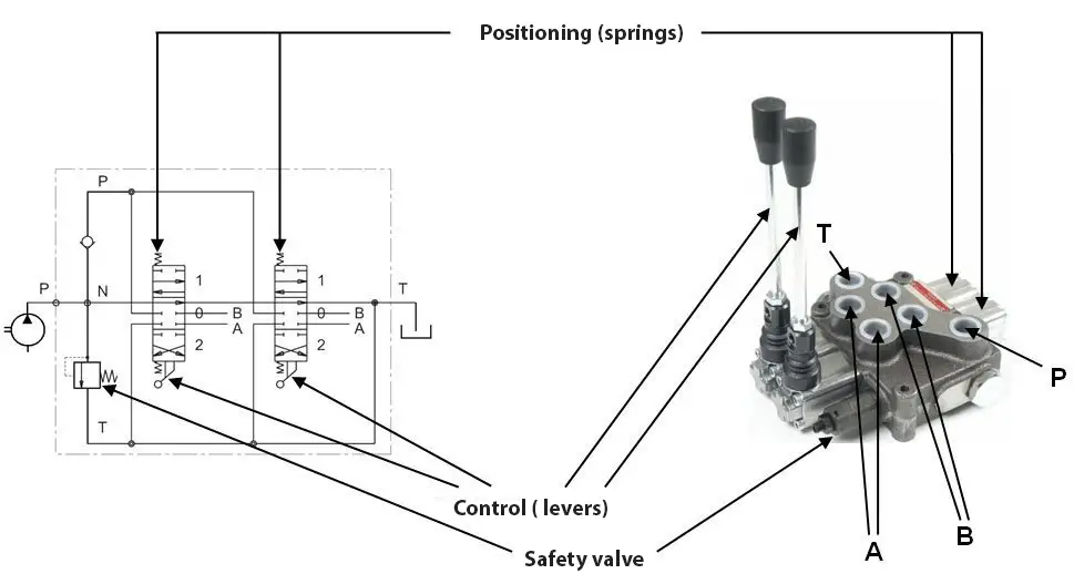
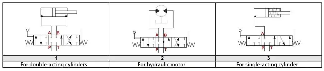
Hydraulic diagram
- number of ways: 4 (number of hose assemblies connected to ports in neutral position)
- number of positions: 2 or 3 (number of squares adjacent to each other)
- 0 (neutral position)
- a, b (actuated position)
- P (pressure/supply passage)
- T (tank/return passage)
- A, B (working passage)
Types of spools
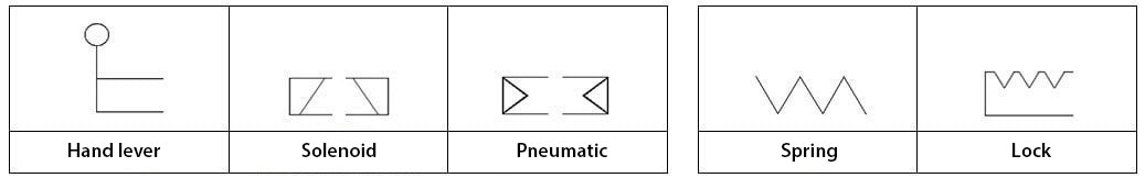
Type of control
Safety valve
| A type | B type | C type | D type |
| without valve | 40 ÷ 80 [bar] | 63 ÷ 200 [bar] | 160 ÷ 315 [bar] |
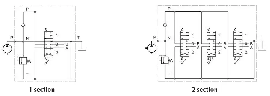
Selection of multi-section directional control valve
During selection consider the following criteria:
- number of sections (1, 2, 3, …)
- size of thread connections
- type of spool (for each section)
- type of control (for each section)
- working pressure
- flow rate
- additional requirements (e.g. lock)
Types of directional control valves
| Type of directional control valve | Nominal flow rate | Max. working pressure (passage A, B, P) | Max. return pressure (passage T) | Max. number of working sections | Connection size | Control |
| YFM35 | 45 l/min | 315 [bar] | 25 [bar] | 6 | 3/8” BSP | levers |
| YFM55 | 60 l/min | 315 [bar] | 25 [bar] | 6 | 1/2″ BSP | levers |
| YE45 | 45 l/min | 250 [bar] | 25 [bar] | 6 | 3/8” BSP | 12V DC |
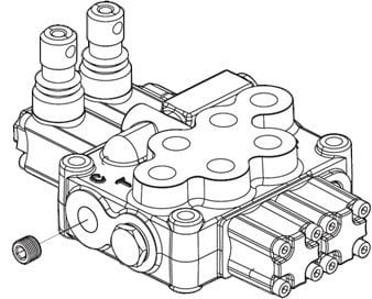
Power beyond function
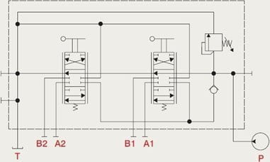
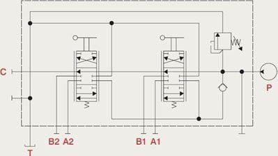
Power beyond – the directional control valves above are equipped with an adapter which, when fitted inside the body, enables operation with a power beyond function. The adapter blocks the direct connection of the pressure passage (P) to the return passage (T). Unused pressurised oil is thus diverted elsewhere in the hydraulic system to feed additional elements.
| normal operation | operation with power beyond function |
 |  |
 |  |
List of products: